
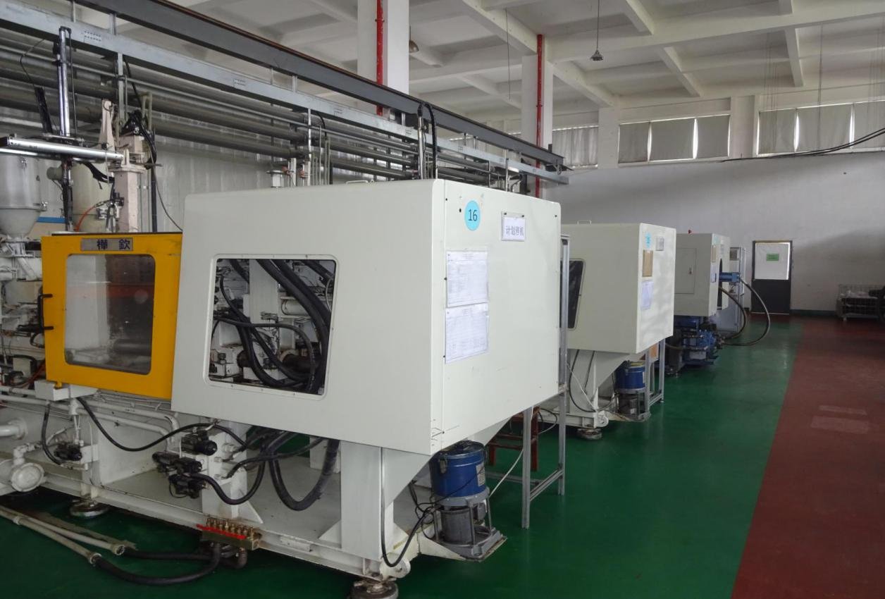
PLASTIC INJECTION MOLDING
Precision starts with the mold.
Mold design, trials, injection production and finishing are planned around the part. From consumer electronics to communications housings, we review appearance, dimensions and assembly before production.
Build the mold around the finished part.
Development follows the part drawing, selected resin and acceptance requirements.
Design for molding
Part drawings, material, tolerances, cosmetic faces and assembly requirements guide mold design.
Mold making and trials
CNC, EDM, measurement and assembly are followed by trials and tooling corrections.
Injection production
Melting, injection, packing and cooling are followed by visual, dimensional and assembly checks.
Zero-draft mold evaluation
Suitable designs can reduce side sliders and their witness lines. Mold geometry and texture require trial confirmation.
Decoration and assembly
Painting, vacuum coating, printing, laser marking and inserts are selected according to requirements, then inspected for finish and fit.
From deep housings to textured surfaces.
The dimensions below describe individual examples, not a universal manufacturing limit. Final specifications are reviewed for each project.
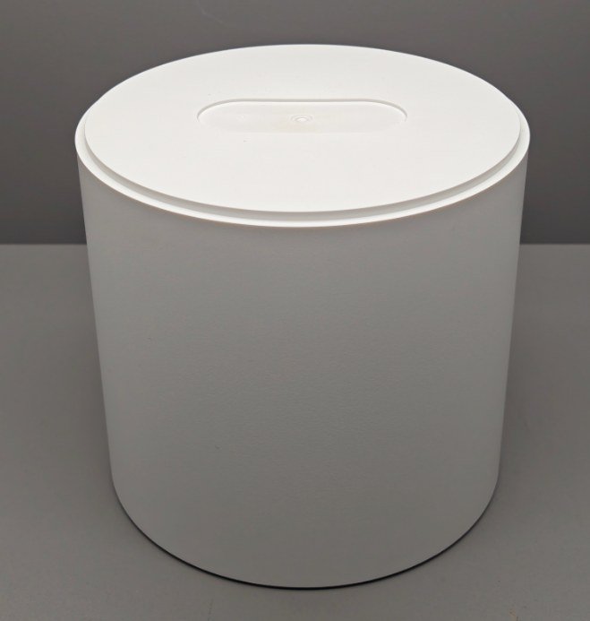
Deep cylindrical housing
Reference example: 150.20 × 150.20 × 141.00 mm; MT10010 texture.
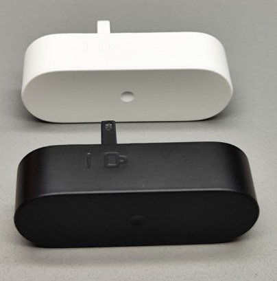
Compact oval housing
Reference example: 43.00 × 15.00 × 11.50 mm; VDI27 texture and 0.10 mm recessed lettering.

Communications enclosure
Cosmetic geometry and internal structure are reviewed together with molding and decoration.
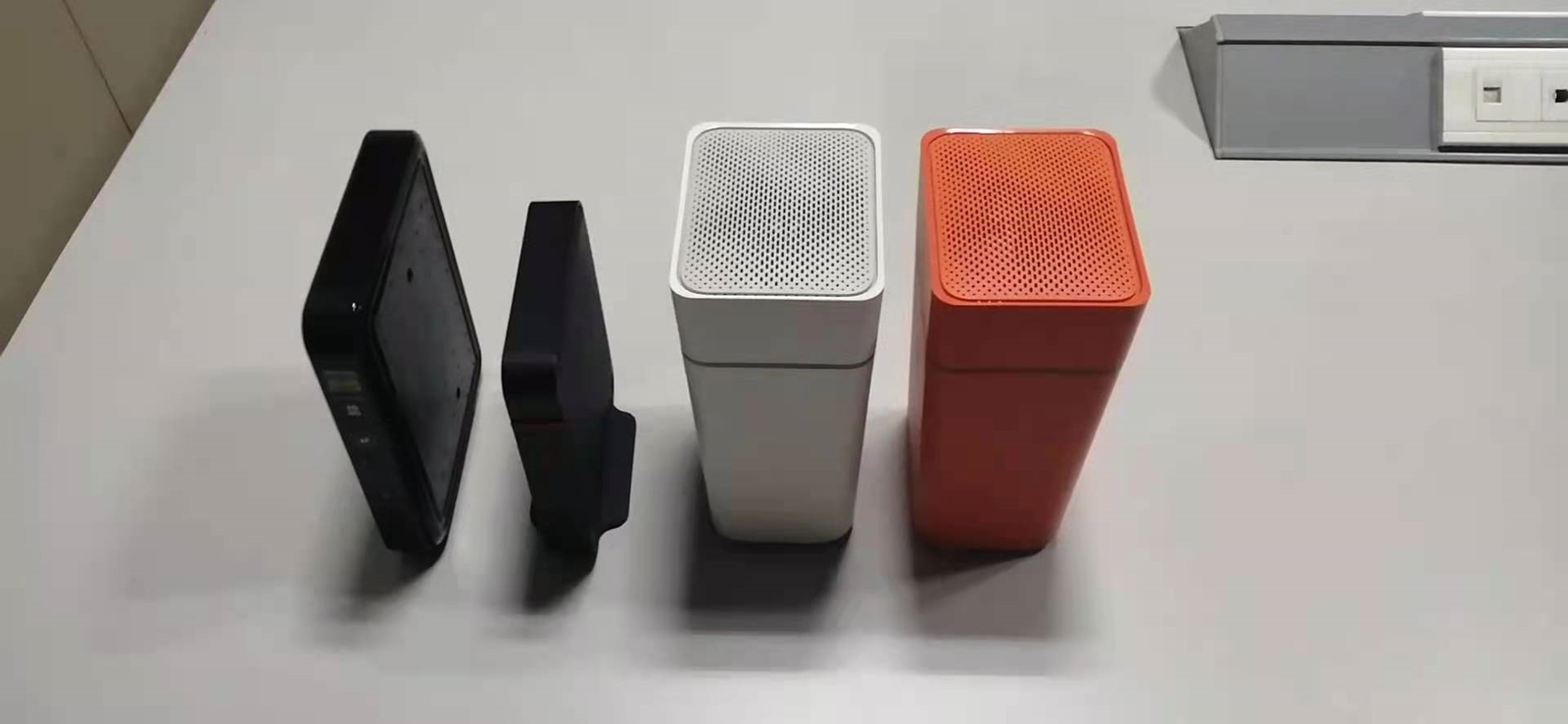
Textured enclosure
Zero-draft and surface-texture requirements are evaluated during tooling development and trials.
Give thin products more room to work.
Evaluate thin bezels, keyboard structures, two-shot parts and LDS antenna carriers around the actual material and mold.
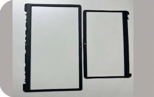
0.45 mm bezel example
The source records a 0.45 mm bezel development example. Final fill, warpage and appearance depend on geometry, resin and mold design.
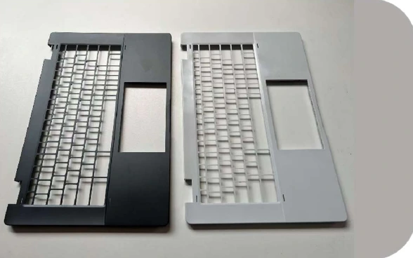
0.90 mm keyboard-area example
The documented 0.90 mm keyboard-area design is a specific component example, not a whole-housing wall specification.
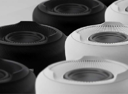
Two-shot molded parts
Review the material pairing, cosmetic boundary and bonding requirements before selecting the mold and molding route.
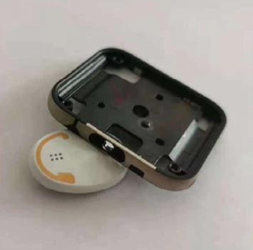
LDS antenna integration
Review antenna layout, laser structuring and metallization together. Electrical performance requires product-level validation.
Compare filling and warpage before tooling decisions.
The source compares conventional and high-speed injection for one NB C-cover model. Results below are simulation outputs for that model, not measured production cycle time or delivery commitments.
| Analysis item | Conventional injection | High-speed injection |
|---|---|---|
| Filling time (s) | 1.391 | 0.1466 |
| V/P switch pressure (MPa) | 180 | 90.29 |
| Overall deformation (mm) | 3.163 | 2.039 |
A composite outer panel can also be evaluated with a thin molded inner structure. Define the joint, dimensional stack-up and qualification plan before choosing the route.
Explore composite structures ↗START A PROJECT
Let’s manufacture what comes next.
Share your design, application or manufacturing challenge.
Talk to our team↗