
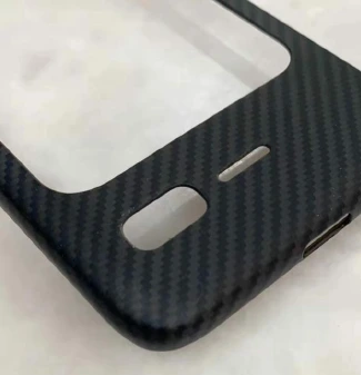
COMPOSITE LIGHTWEIGHT COMPONENTS
Less weight. More room for design.
CFRP and GFRP housings connect fiber layup, compression molding, precision machining and decoration. Review thin walls, PMI sandwich structures and plastic interfaces together.
Plan the laminate around the product.
Fiber type alone does not define the finished part. Resin, ply direction, core and interfaces determine the route.
CFRP and PMI sandwich structures
UD carbon plies and PMI cores can be evaluated for thin housings. Layup direction and reinforcement are reviewed around loads and mounting points.
GFRP and thermoplastic forming
Select a thermoplastic or thermoset resin system for the application. Processing, storage and secondary joining requirements differ between systems.
Textured exterior components
Coordinate weave, edge geometry, openings and coating requirements for the exterior surface.
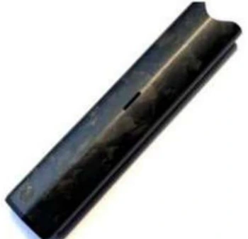
Curved composite housings
Evaluate bend geometry and layup around corner radii, thickness transitions and the selected finish.
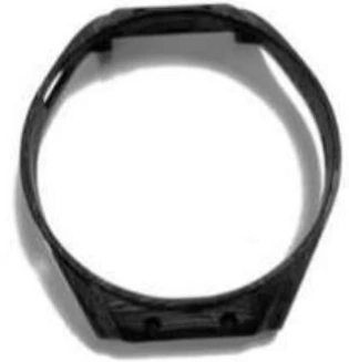
Wearable structural frames
Reference product geometry for compact openings, mounting features and downstream fit review.
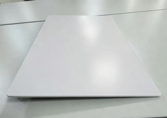
Thin laptop housing
A documented M40 / PMI / M40 housing combines 0.7 mm thickness with a 56 g example weight.
0.7 mm. 56 g. One defined housing example.
These values describe one M40 / PMI / M40 component. They are not universal production limits or a weight comparison against another part.
| Item | Documented value |
|---|---|
| Housing thickness | 0.7 mm |
| Side-wall thickness | 0.7 mm |
| Example weight | 56 g |
| Material structure | M40 / PMI / M40 |
| Layup count | 5 |
| Corner radius | R0.3 |
| Coating layers | 3 |
Connect layup, forming and assembly.
Material and resin selection
Select CFRP or GFRP, resin type and, where appropriate, a PMI core around stiffness, temperature and finish requirements.
Cutting and layup
Plan ply direction, symmetry and local reinforcement; define material storage according to its resin system.
Compression molding
Set the mold, temperature, pressure and time around the laminate and part geometry.
Machining and edge control
Machine outlines, holes and interfaces with suitable fixtures and checks for edge damage.
Decoration and assembly
Review sanding, coating, inserts and bonding according to surface quality and assembly requirements.
Inspection and qualification
Agree dimensional, appearance, bonding and functional checks before accepting the part.
For evaluation, share the drawing, weight target, material or fiber preference, wall thickness, loads, cosmetic finish, annual volume and assembly method. Antenna, charging, impact and thermal performance require product-level testing.
Discuss a composite component ↗PROCESS CHOICES & DOCUMENTED EXAMPLES
Lose weight where the structure allows it.
A sandwich core and local layup let the cover balance stiffness, wall thickness and assembly requirements.
Swipe the table sideways to compare all columns.
| Same documented cover | Value | Design implication |
|---|---|---|
| Wall / sidewall | 0.7 / 0.7 mm | Evaluate edge details and machining allowance together. |
| Finished example weight | 56 g | Specific to the illustrated cover, not a universal weight reduction ratio. |
| Construction | M40 + PMI + M40; 5 layers | Includes the source example of a three-coat finish. |
CFRP and GFRP are not electrically equivalent. Confirm antenna location, fiber orientation and RF testing rather than assuming every composite cover passes wireless signals.
START A PROJECT
Let’s manufacture what comes next.
Share your design, application or manufacturing challenge.
Talk to our team↗