
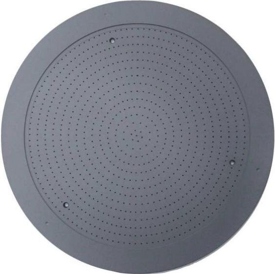
WAFER HOLDING COMPONENTS
Porous ceramic vacuum chucks.
Uniform vacuum distribution and precision surfaces support stable wafer holding in dicing, grinding, polishing, bonding and transfer processes.
Three holding structures for different wafer-process requirements.
Structure selection considers workpiece size, vacuum distribution, contact area, flatness and the equipment mounting interface.
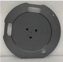
Microporous ceramic vacuum chuck
A fine-pore working surface distributes vacuum over the holding area. Base geometry, ports and mounting features are evaluated around the target equipment.
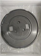
Concentric-groove vacuum chuck
Concentric grooves guide vacuum distribution across the circular work surface for positioning and holding applications.
Perforated-array vacuum chuck
A regular circular hole array provides a distributed vacuum interface for wafer carrying and holding. Hole layout and flatness are confirmed by application.
Holding performance depends on the complete interface.
Uniform vacuum distribution
A controlled pore or vacuum-path structure distributes suction across the work surface to reduce concentrated holding force and support repeatable positioning.
Material & pore selection
Supplied porous-ceramic data covers alumina and SiC, pore sizes from 2–100 μm and porosity from 20% to above 90%. The final combination is selected around flow, strength, cleanliness and electrical requirements.
Flatness by working size
Verified reference values are below 2 μm for 4- and 6-inch sizes, below 3 μm for 8-inch and below 5 μm for 12-inch. Final values depend on base, mounting and process conditions.
Processes & equipment interface
Applications include dicing, grinding, polishing, bonding, laser processing and wafer transfer. Vacuum ports, base geometry and mounting features are reviewed against the target equipment.
PROCESS CHOICES & DOCUMENTED EXAMPLES
Spread the vacuum, not the point load.
Porous ceramic distributes suction through connected pores. Select pore structure together with airflow, strength and the workpiece surface.
Swipe the table sideways to compare all columns.
| Wafer format | Example flatness | Example pore structure |
|---|---|---|
| 4 / 6 inches | <2 μm | 20–50 μm pores; 35–55% porosity |
| 8 inches | <3 μm | Alumina or SiC; antistatic option listed |
| 12 inches | <5 μm | Confirm base material and sealing perimeter |
These wafer-chuck examples are narrower than the broader 2–100 μm material pore range. Do not combine the best values from different products into one specification.
START A PROJECT
Let’s manufacture what comes next.
Share your design, application or manufacturing challenge.
Talk to our team↗